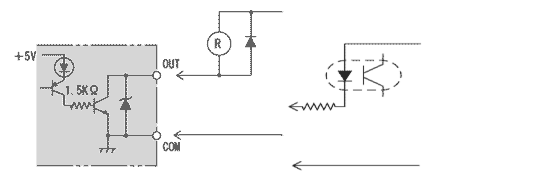
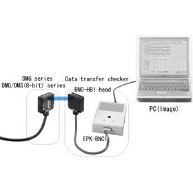
NPN open-collector output
35DC 50mA residual voltage 1.5V or less
| Connector (1) |
|
Connector (2) |
| Colors |
Pin No. |
Functions |
Colors |
Pin No. |
Functions |
| Pale blue |
1 |
Power 0V |
Green / black |
1 |
GO*3 |
| Pink |
2 |
Power +V |
Blue |
2 |
STROBE*4 |
| White |
3 |
IN1 |
- |
3 |
- |
| White / black |
4 |
IN2 |
Purple |
4 |
OUT8 |
| Brown |
5 |
IN3 |
Purple / black |
5 |
OUT7 |
| Brown / black |
6 |
IN4 |
Gray |
6 |
OUT6 |
| Red |
7 |
IN5 |
Gray / black |
7 |
OUT5 |
| Red / black |
8 |
IN6 |
Pink / black |
8 |
OUT4 |
| Orange |
9 |
IN7 |
Pale blue / black |
9 |
OUT3 |
| Orange / black |
10 |
IN8 |
Pink/red |
10 |
OUT2 |
| Yellow |
11 |
MODE*1 |
Yellow/red |
11 |
OUT1 |
| Yellow / black |
12 |
COM(0V) |
- |
12 |
- |
| Green |
13 |
SELECT*2 |
- |
13 |
- |
| Shield |
Shield |
*1 MODE input
This is to choose transmission/reception mode when standing by
*Transmission stand-by mode by opened between mode and I/O COM
*Reception stand-by mode by short-circuited between mode and I/O COM
Note) If one side is set to transmission stand-by mode, other one should be set to reception standby mode.
*2 SELECT input
This is to stop transmission/reception optionally by outer signal
*Operating by opened between select and I/O COM
*Stopping by short-circuited between select and I/O COM
*3 GO output
This is to check correct optical single
*ON when receiving correct optical axis
*OFF when interrupting optical axis(Not-receiving)
*4 Strobe
It is getting ON when data is fixed.
Note) The connector attached can't be used as relay terminal.